Are you looking for an answer to the topic “Control System – Signal Flow Graphs – ElectronicsGuide4u“? We answer all your questions at the website Chambazone.com in category: 40+ Marketing Blog Topics & Ideas. You will find the answer right below.
Keep Reading
Table of Contents
Introduction to Signal Flow Graphs
Images related to the topicIntroduction to Signal Flow Graphs
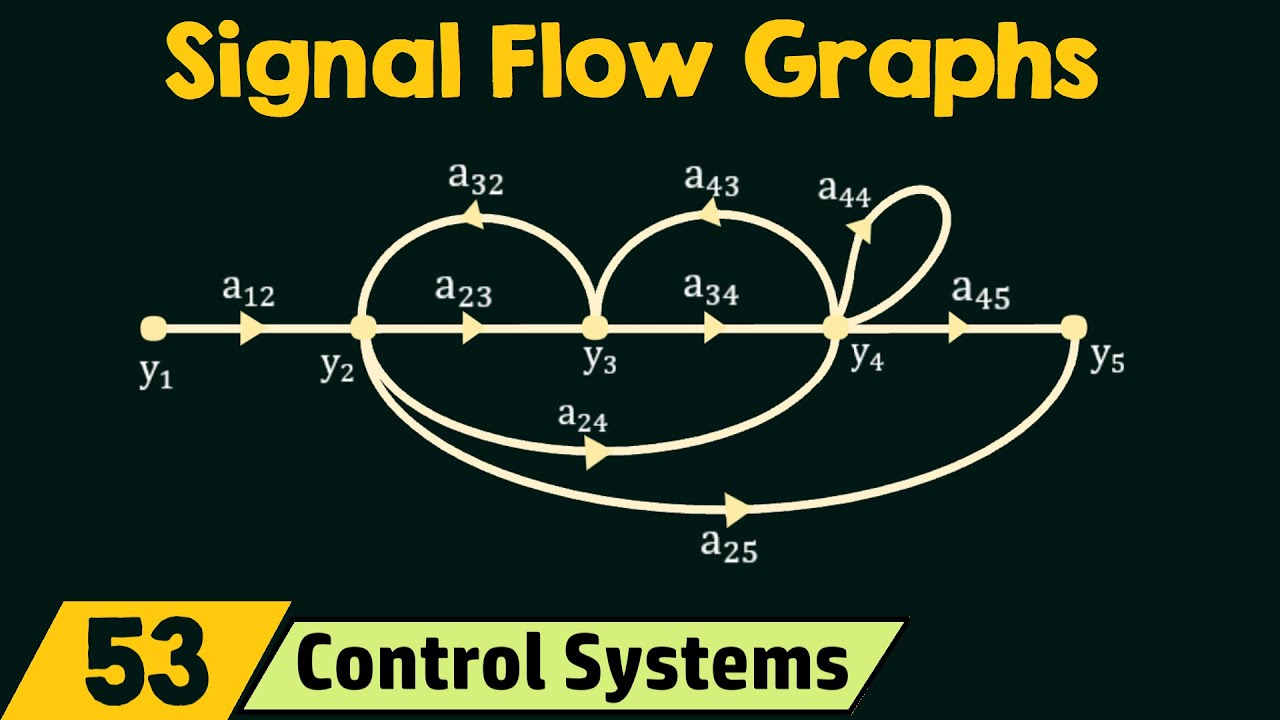
Signal flow graphs are an alternative to block reduction techniques. Here, we are dealing with branches and nodes, not blocks, branch points, sum points, etc. Significance of Signal Flow Graphs and Block Reduction Techniques Both methods can help us find the overall transfer function of the system. In the case of block reduction techniques, we must analyze the entire system in reduced fractions. In the case of complex systems, finding the overall transfer function becomes very tedious. Signal flow graphs, on the other hand, use a single formula called the “Merson’s gain formula” to achieve the same result (and therefore require less time and effort). Let us first understand how to draw a signal flow graph from an equation and then use it to control a system. Each rule system consists of nodes (dependent and independent variables). These nodes are connected by a line called a “branch”. Conser the simple equation here, called “node”, where “A” is the gain. Arrows indicate the direction of signal flow. Let’s take an example to clarify this topic. Conser a system represented by the following equations: ; ; ; We will first plot the SFG of the indivual equations and then the combined SFG. 2nd 3rd 4th Now if we combine all the numbers above, we can get the following signal flow graph (consisting of 5 variables):.
Method to draw Signal flow graph that can be deduced from any Block Diagrams
We will now see how to draw a signal flow graph from a block diagram, for this we have to follow these steps: Represent each summation point and each start point as a separate node. Connect each node with a branch. The block transfer function is represented as branch gain. The input and output nodes are shown separately, with a branch gain of 1. Let’s take an example to illustrate this more clearly. We now represent the block diagram as a signal flow graph: we can entify the nodes of the SFG by subtracting summation points and marker points. Finally, a signal flow graph can be represented as follows: As we saw above, we can easily derive a signal flow graph from a complex block diagram. Finally, we have to learn some methods to reduce the signal flow graph consisting of any number of branches and nodes. Some Important Signal Flow Diagram Terminology Now let’s learn some common terms that we may encounter when simplifying a system using the Signal Flow Diagram approach. 1. Source node or entry node A source node can be defined as a node with only output branches. 2. Output or sink node This node has only incoming branches. 3. Chain node This node has incoming and outgoing branches 4. Forward path This is the path from the input to the output node is the forward path 5. Feedback path (or feedback loop) A path (node) that starts and ends at the same point . If it consists of only one node in self-loop 6, it can be called a “self-loop”. Path Gain The product of all branch gains while traversing the forward path is called the path gain. This is the path gain of paths x1-x2-x3-x4 A x B x C. 7. Paths This can be found by looking at the connected branches, each path is on the path of the signal flow and no node is traversed more than once. 8. Contacting Paths A loop and a path are sa to be in contact when they share a node. Even if there are one or more common nodes in the loop, they are called contact loops. 9. Contactless Rings If there is no common node between any rings, they are called contactless rings. 10. Loop gain Simply put, it is the product of all branch gains to form a loop, which is called loop gain. For the x2-x3-x5-x2 path, the loop gain is L1 x L2 . 11. Dummy Nodes Branches with a gain of “1” can be added to inputs and outputs. They cannot be added between links. This addition does not affect the transfer function in any way. Properties of SFG (Signal Flow Graph) Any block diagram can be represented by an SFG, but not vice versa. It only works for time-invariant linear systems. The variable value for each node is equal to the algebraic sum of all signals entering that node. The gain of the SFG is given by Mason’s equation. In the next article, we will see how to implement these rules using signal flow graph techniques (using Mersen’s equations) to reduce any complex block diagram system. report this ad
What is signal flow graph in control system?
“A signal-flow graph is a diagram that represents a set of simultaneous algebraic equations. When applying the signal flow graph method to analysis of control systems, we must first transform linear differential equations into algebraic equations in [the Laplace transform variable] s..”
Why is SFG used?
It represents a network in which nodes are used for the representation of system variable which is connected by direct branches. SFG is a diagram which represents a set of equations. It consists of nodes and branches such that each branch of SFG having an arrow which represents the flow of the signal.
What are the basic properties of SFG?
- Signal Flow Graphs are applicable to linear systems.
- It consists of nodes and branches. …
- A node adds the signals of all incoming branches and transmits this sum to all outgoing branches.
- Signals travel along branches only in a marked direction and is multiplied by the gain of the branch.
What is CFG in software engineering?
A Control Flow Graph (CFG) is the graphical representation of control flow or computation during the execution of programs or applications. Control flow graphs are mostly used in static analysis as well as compiler applications, as they can accurately represent the flow inside of a program unit.
How many loops does the given SFG have?
A loop is a path that originates and terminates on the same node and along which no other node is encountered more than once. For example, there are four loops in the SFG of Fig.
What are the properties of signal graphs?
Properties of Signal Flow Graph
The signal from a node to other flows through the branch in the direction of arrowhead. The graphical method is valid only for linear time-invariant systems. The signal flowing through a branch is multiplied by the gain or transmittance of that branch.
What is signal flow graph in DSP?
A signal flow graph is a network of directed branches that connect at nodes. It is equivalent to block diagrams which we are already familiar with, except for a few notational differences. As examples, OSB Figures 6.8 and 6.9 depict the general form of signal flow graphs.
Which system are signal flow graphs applicable?
Assertion (A): Signal flow graph is applicable to the linear systems. Reason (R): Signal flow graph method of finding the transfer function of a system is very simple and does not require any reduction technique.
What are the elements of flow graph?
o The control flow graph is a graphical representation of a program’s control structure. It uses the elements named process blocks, decisions, and junctions.
What are the advantages of signal flow graph?
The advantage in signal flow graph method is that, using Mason’s gain formula the overall gain of the system can be computed easily. This method is simpler than the tedious block diagram reduction techniques.
See some more details on the topic Control System – Signal Flow Graphs – ElectronicsGuide4u here:
Control Systems – Signal Flow Graphs – Tutorialspoint
Signal flow graph is a graphical representation of algebraic equations. In this chapter, let us discuss the basic concepts related signal flow graph and …
Control System Signal Flow Graphs – javatpoint
Signal Flow Graph (SFG) · It represents a network in which nodes are used for the representation of system variable which is connected by direct branches. · SFG …
Signal Flow Graph of Control System – Electrical4U
Signal flow graph of control system is further simplification of block diagram of control system. Here, the blocks of transfer function, …
Control Systems/Signal Flow Diagrams – Wikibooks
Control Systems/Signal Flow Diagrams · Contents · Signal-flow graphsEdit · ExamplesEdit · Electrical engineering: Construction of a flow graph for a RC circuitEdit.
Related searches to Control System – Signal Flow Graphs – ElectronicsGuide4u
- signal flow graph solver
- control system flow diagram
- sfg tutorial
- control system signal flow graphs 4u pdf download
- control system signal flow graphs 4u pdf free download
- control system signal flow graphs 4u pdf
- control system graph
- signal flow graph reduction rules
- difference between block diagram and signal flow graph
- signal flow graph to block diagram
- convert transfer function to signal flow graph
Information related to the topic Control System – Signal Flow Graphs – ElectronicsGuide4u
Here are the search results of the thread Control System – Signal Flow Graphs – ElectronicsGuide4u from Bing. You can read more if you want.
You have just come across an article on the topic Control System – Signal Flow Graphs – ElectronicsGuide4u. If you found this article useful, please share it. Thank you very much.