Are you looking for an answer to the topic “Control System – Solved Example of Block Reduction Technique – ElectronicsGuide4u“? We answer all your questions at the website Chambazone.com in category: 40+ Marketing Blog Topics & Ideas. You will find the answer right below.
Keep Reading
Table of Contents
Block Diagram Reduction (Solved Example 1)
Images related to the topicBlock Diagram Reduction (Solved Example 1)
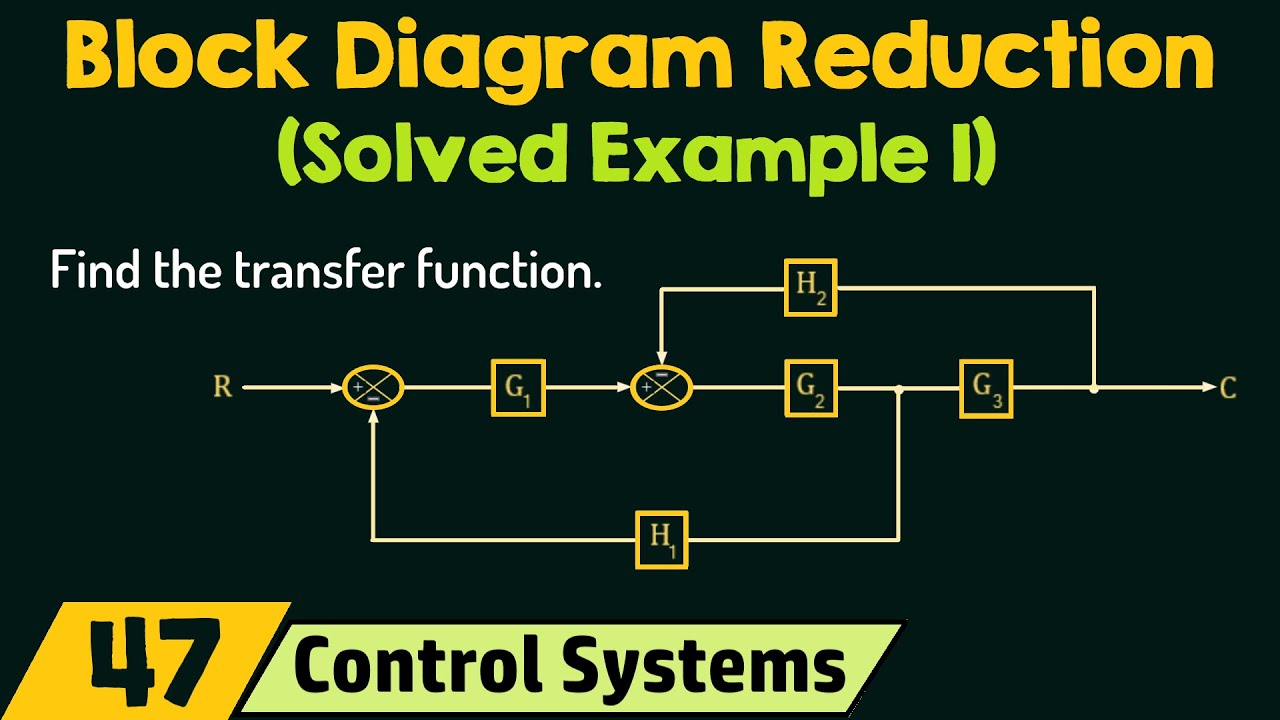
You must already know all the basic rules for flattening complex block diagrams. Now that we need to implement these rules, we’ll see how the block diagram reduction technique actually works. You can get help from some of the other standard books in Control System to practice more numbers to make this topic easy. In this post, each step is linked to a reference diagram to help you understand the rules clearly. I ask you to check the problem first (without looking at the solution) after trying to verify a given solution. Looking at the graph below, we are interested in finding the ratio C(s)/R(s) (the total transfer function of the system). Now we should apply the various rules we learned in the previous article to solve this complex block diagram. Given the block diagram, blocks G4, G3, and G5 are obviously parallel. So we should apply rule 2 first (see image below). Now the blocks G2 and G3 + G4 + G5 are concatenated (arrays), so now we should apply rule 1 to get G2 and (G3 + G4 + G5) as a result. (See figure below) 3. Rule 3 can now be applied to feedback loop G1-H1. As shown in the figure below: 4. Now rule 1 can be used for cascading blocks (connected in series) in forward path and G2 (G3 + G4 + G5). You can refer to the following diagram: 5. Now we can use rule 3 on the loop with the feedback block. We can now use rule 3, where , and H(s) = H2 6. Finally, we need to apply rule 1 (because we are now left with the G6 block in series with the resulting block diagram). The simplified block diagram is shown below: Applying rule 1 we get: So it is obvious from the above example that we can easily reduce a complex block diagram system to a simple block diagram system by using the block reduction rule. Stay tuned for more interesting topics in the next article. report this ad
What are the block diagram reduction techniques explain with one example?
Rule 1 − Check for the blocks connected in series and simplify. Rule 2 − Check for the blocks connected in parallel and simplify. Rule 3 − Check for the blocks connected in feedback loop and simplify. Rule 4 − If there is difficulty with take-off point while simplifying, shift it towards right.
What is a control system explain with block diagram and an example?
The basic elements of a block diagram are a block, the summing point and the take-off point. Let us consider the block diagram of a closed loop control system as shown in the following figure to identify these elements. The above block diagram consists of two blocks having transfer functions G(s) and H(s).
What are the various rules for block reduction technique explain any seven of them?
- Rule 1: Blocks in cascade/series.
- Rule 2: Blocks in parallel.
- Rule 3: Feedback loop elimination.
- Rule 4: Associative law for summing.
- Rule 5: Shifting a summing point before a block.
- Rule 6: Shifting a summing point after a block.
- Rule 7: Shifting take-off point before a block.
What is meant by block diagram reduction technique?
A pictorial representation of the functions performed by each component and of the flow of signals. Block diagram. A pictorial representation of the functions performed by each component and of the flow of signals.
How do you write a block diagram?
- Click the File tab.
- Click New, under templates, or categories, click General, and then double-click Block Diagram.
- From the Blocks and Blocks Raised stencils, drag shapes onto the drawing page.
- To add text to a shape, select the shape and then type.
What is control system with example?
A control system manages, commands, directs, or regulates the behavior of other devices or systems using control loops. It can range from a single home heating controller using a thermostat controlling a domestic boiler to large industrial control systems which are used for controlling processes or machines.
Why block diagram is used in control system?
Block diagrams are used to simplify complex control systems. Each element of the control system is represented with a block, and the block is the symbolic representation of that element’s transfer function. A complete control system can be represented with a required number of interconnected blocks.
What is block diagram in feedback control system?
An important factor to remember is that the block diagram represents flowpaths of control signals, but does not represent flow of energy through the system or process. Below are several terms associated with the closed-loop block diagram.
What is the simplest form of the block diagram?
The simplest form of a block diagram is the block and arrows diagram. It consists of a single block with one input and one output (Figure 1A). The block normally contains the name of the element (Figure 1B) or the symbol of a mathematical operation (Figure 1C) to be performed on the input to obtain the desired output.
What is block diagram of computer?
A Block diagram of a computer displays a structural representation of a computer system. The block diagram gives you a quick overview of the working process of a computer from inputting the data to retrieving the desired results.
How do you block G1 and G2 connected in parallel are combined?
Parallel Connection
In the following figure, two blocks having transfer functions G1(s) and G2(s) are connected in parallel. The outputs of these two blocks are connected to the summing point. Compare this equation with the standard form of the output equation, Y(s)=G(s)X(s).
What is the control system?
A control system is a set of mechanical or electronic devices that regulates other devices or systems by way of control loops. Typically, control systems are computerized. Control systems are a central part of industry and of automation.
What are the types of control system?
- Open loop control systems (non-feedback control systems)
- Closed loop control systems (feedback control systems)
See some more details on the topic Control System – Solved Example of Block Reduction Technique – ElectronicsGuide4u here:
Control Systems – Block Diagram Reduction – Tutorialspoint
Example. Conser the block diagram shown in the following figure. Let us simplify (reduce) this block diagram using the block diagram reduction rules.
Using Block Diagrams – Wescott Design Services
Figure 2 is an example of a block diagram showing a simple closed-loop control system. The diagram details a controller, and shows a plant with no detail.
Block diagram Examples – SlideShare
Examples regarding BLock Diagaram. contains almost 8 examples with complete solution step by … Control System Engineering Kuntumal Sagar M. B.TECH (E.E) …
Control System Block Diagram – javatpoint
Example. Find the transfer function of the following by block reduction technique. Block Diagram in control systems. Solution. Step 1: …
Related searches to Control System – Solved Example of Block Reduction Technique – ElectronicsGuide4u
- block diagram reduction online solver
- reduce the system to a single transfer function
- block diagram reduction with multiple inputs
- block diagram manipulation
- find the transfer function of the following block diagram
- controller block diagram
- block diagram reduction with disturbance
- block diagram reduction rules pdf
Information related to the topic Control System – Solved Example of Block Reduction Technique – ElectronicsGuide4u
Here are the search results of the thread Control System – Solved Example of Block Reduction Technique – ElectronicsGuide4u from Bing. You can read more if you want.
You have just come across an article on the topic Control System – Solved Example of Block Reduction Technique – ElectronicsGuide4u. If you found this article useful, please share it. Thank you very much.